
In this guide
A wet central-heating system is easiest to understand as one connected loop. The heat source, pump, pipework, radiators and controls each have a different job, but comfort depends on them working together. Once you can follow that loop, it becomes much easier to describe uneven heating, compare controls or prepare for radiator and valve work.
Start with the heating loop
A boiler or another heat source transfers energy to the water in the heating circuit. A pump, which may be built into the appliance or installed elsewhere in the system, circulates that water through the flow pipework. Radiators or other emitters release some of the heat into the rooms, and cooler water returns to the heat source to be reheated.
Controls decide when there is a demand for heat and can limit how much heat reaches particular rooms. The system also needs a way to accommodate expansion as the water warms, along with the appropriate valves and safety devices. Those details differ between sealed and open-vented arrangements, so the components and checks in one home may not match another.
This is why a symptom at one radiator does not automatically identify a faulty radiator, valve or boiler. The cause can sit elsewhere in the hydraulic loop or in the controls that tell it when to operate.
Separate space heating from hot water
The water circulating through radiators is part of the space-heating circuit. It is not the same water delivered at the taps, even where one boiler serves both jobs. A combi boiler commonly heats domestic hot water on demand without a storage cylinder. Other systems may store hot water in a cylinder and use a separate control path to call for heat.
In a cylinder system, the cylinder thermostat monitors the stored-water temperature and works through the system controls to start or stop a heat demand. It does not simply let more heating water into the cylinder. An immersion heater is a separate electrical heat source with its own control and safety requirements.
Before interpreting a control or planning a change, first establish whether the property uses a combi arrangement, a stored hot-water cylinder or another configuration. That prevents space-heating and domestic-hot-water controls from being confused.
Single-pipe and two-pipe layouts behave differently
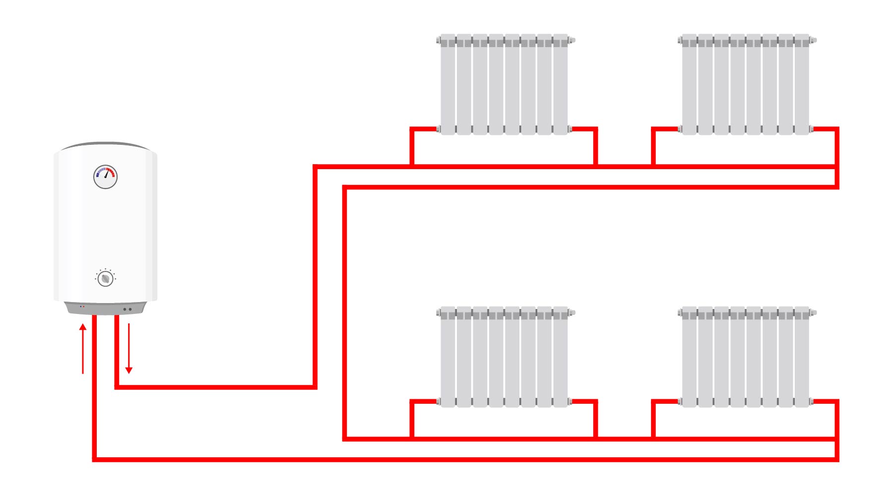
In a single-pipe system, radiators sit around a shared circulation loop. Water conditions can change as the circuit progresses, so one alteration may affect heat delivery elsewhere. The diagram below is one simplified single-pipe example, not a universal plan for every installation.
A two-pipe system uses separate flow and return mains, with each radiator connected across them. This supports more independent branches and gives every radiator a route from the flow main to the return main. It still relies on suitable pipe sizing, pump performance and system balancing so water is distributed as intended.
You cannot reliably identify the complete layout from which side of one radiator feels warm first. Hidden pipe routes, valve type and installation design all matter. If the layout needs to be mapped for an alteration, use a competent heating professional rather than making assumptions from visible tails alone.
Microbore uses manifold-fed branches
A microbore system normally carries flow and return water to manifolds, then uses paired small-bore branches to individual radiators. Short, flexible branches can help with routing through confined spaces, but that practical benefit does not make every microbore layout simple or automatically efficient.
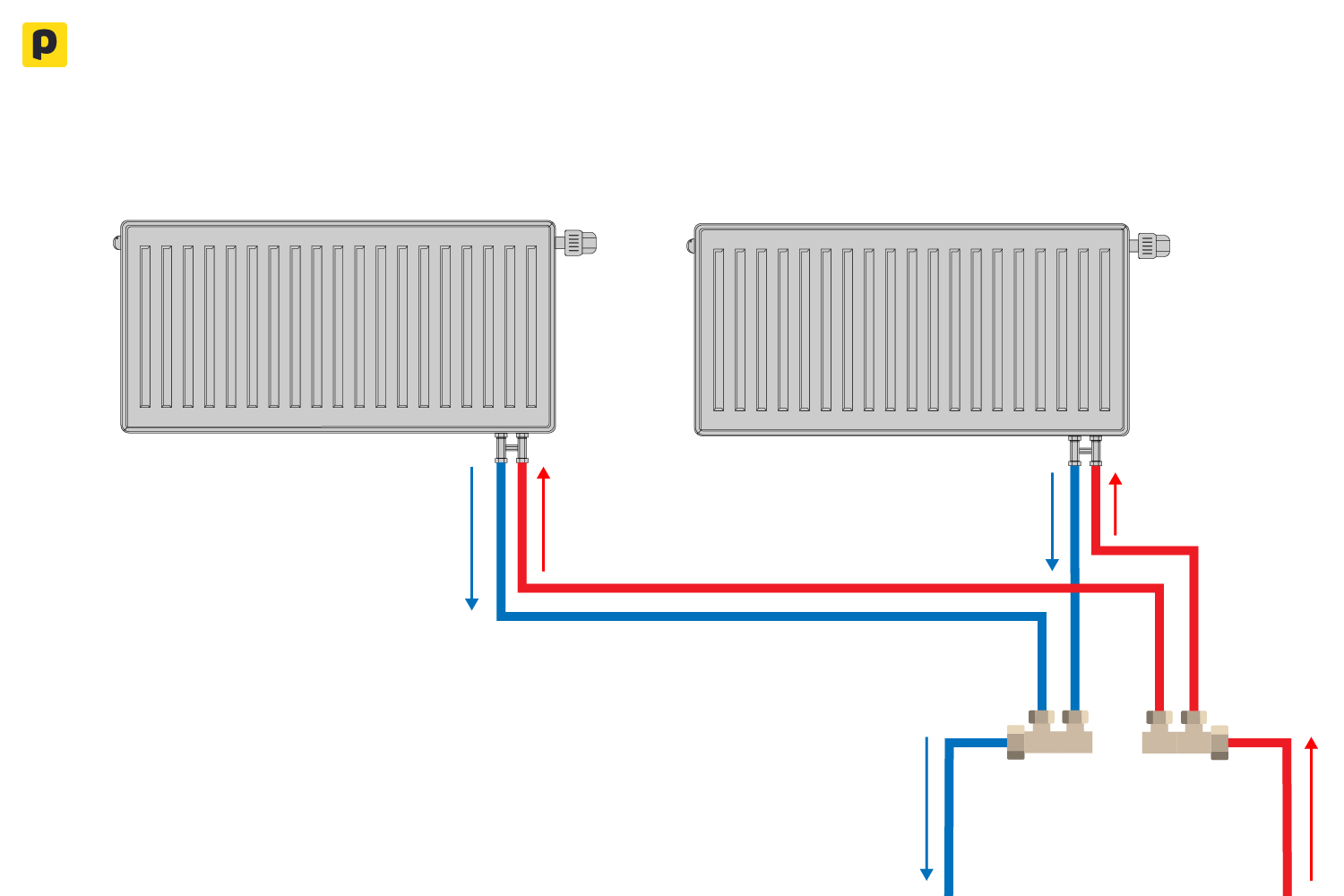
Performance depends on branch length, pipe resistance, radiator heat demand, cleanliness and the overall hydraulic design. Existing systems also use different diameters and arrangements. Any replacement radiator, valve or pipe alteration must therefore be checked against the actual system rather than a generic microbore rule.
Radiators release heat in two ways
Hot system water transfers energy to the radiator metal. The warmed radiator then heats the room through both natural convection and thermal radiation. Air near the radiator warms and rises, cooler air moves in to replace it, and a circulation pattern develops through the room.
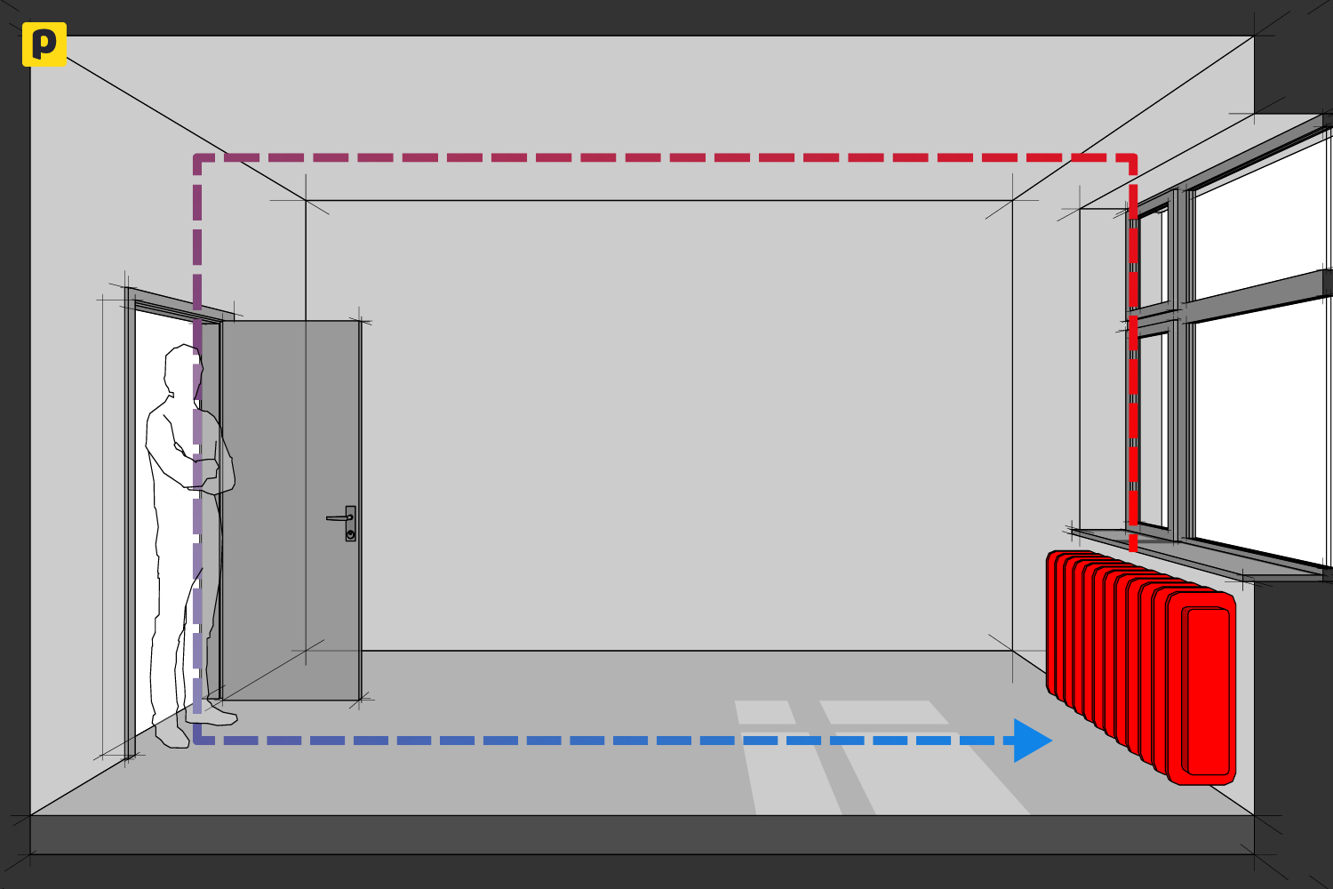
Radiator output is not determined by appearance alone. Size and design, system-water temperature, room temperature, available flow, valve position, balancing and nearby obstructions all influence the result. Furniture and some radiator covers can interfere with air movement, while an undersized or unsuitable emitter cannot be corrected by turning a control higher.
For a closer look at heat transfer, valves and emitter selection, read How a Radiator Works.
Heating controls have different jobs
Controls work best when each one is understood by its role:
- A programmer or schedule sets the periods when heating is available.
- A room thermostat responds to the air temperature in a representative location and creates or ends the main heat demand.
- A thermostatic radiator valve, or TRV, responds to the air around one radiator and modulates water flow through that emitter.
- Smart controls may add remote access, zoning or adaptive features, but the available functions depend on the product and system design.
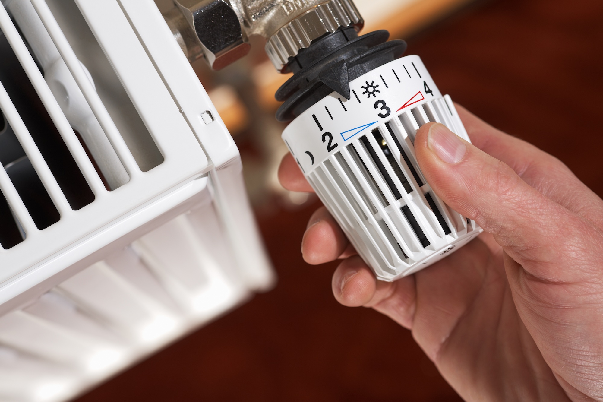
A TRV normally does not replace the main boiler interlock, and its numbered dial is not a guaranteed room-temperature scale. Its local surroundings matter, which is why it should not be treated as a precise thermometer. Room-thermostat location matters too: draughts, direct heat and other local influences can make one position unrepresentative.
Radiator Valves Explained compares the roles of manual, thermostatic and lockshield valves. For a more focused control guide, see Thermostatic Radiator Valves Explained, then compare the Thermostatic Radiator Valves collection only after confirming compatibility with the radiator and system.
Controls can reduce waste, not guarantee savings
Scheduling heat for the times it is wanted, avoiding unnecessary room temperatures and limiting heat in less-used spaces can reduce avoidable demand. The actual effect on energy use and bills depends on the building's heat loss, weather, tariffs, system condition, settings and how the home is used.
There is no universal bill-saving percentage for lowering a thermostat, and a programmer is not inherently inefficient. A smart control is not automatically the lowest-energy choice either. The useful question is whether the controls suit the system, are positioned and configured correctly, and help the household avoid heating that is not needed.
Read symptoms in system context
When the heating does not behave as expected, start by describing the pattern rather than naming a fault. Useful observations include:
- whether the issue affects the whole home, one branch or one radiator;
- whether the heat source appears to respond when the user-accessible controls call for heat;
- whether the problem follows a schedule, room-thermostat setting or local radiator-control setting; and
- whether the behaviour is constant or changes as the system warms.
These observations help a professional narrow the system area that needs attention, but they are not a diagnosis. Touch alone cannot prove which pipe is flow or return, whether a valve is faulty or why a radiator has a cold area.
Repeated pressure changes, water leaks, electrical faults, persistent cold areas or unexplained noise need competent assessment. Follow the appliance and control manuals for user-accessible checks only. Do not open appliance covers, work on gas or electrical components, drain or pressurise the circuit, balance the system or alter valves and pipework without the required competence.
Map the system before changing components
Before replacing a radiator, valve or control, establish:
- the heat source and whether the system is sealed or open vented;
- the pipe layout, including any single-pipe, two-pipe or microbore sections;
- the existing control logic and domestic-hot-water arrangement;
- the room heat-loss and emitter output needed at the intended flow temperature;
- the connection route, access and valve pattern; and
- the product compatibility, manufacturer requirements and applicable UK rules.
This system map helps avoid buying a component that fits visually but does not suit the hydraulics, controls or required output. It also gives a heating professional the information needed to plan sizing, balancing, commissioning and any wider work.
Once those checks are complete, browse the Radiator Valves range to compare suitable patterns and control types for the next stage of the project.